Finished project.
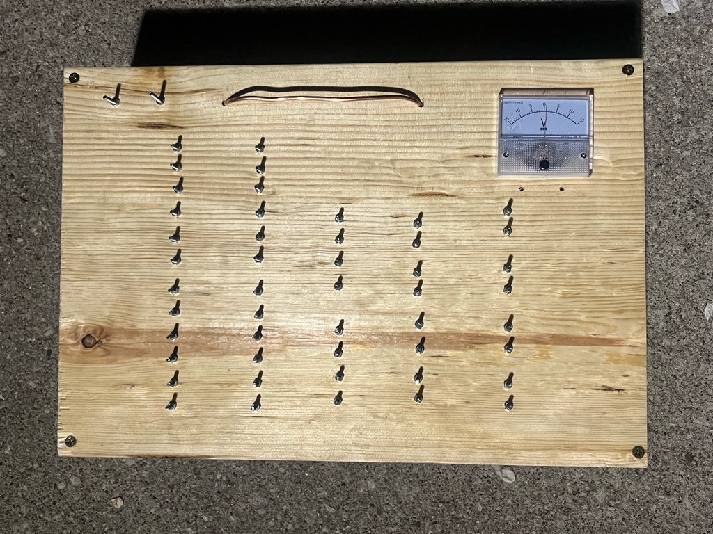
Front panel layout for interfacing.
Introduction
I made a basic proof-of-concept analog computer using the TL082 op-amp chip.
This computer can be made DIY using the paper circuits I designed. I decided to make the paper circuits in modules so a computer can be built using however many of each one desires.
Finished project.
Front panel layout for interfacing.
Functionality
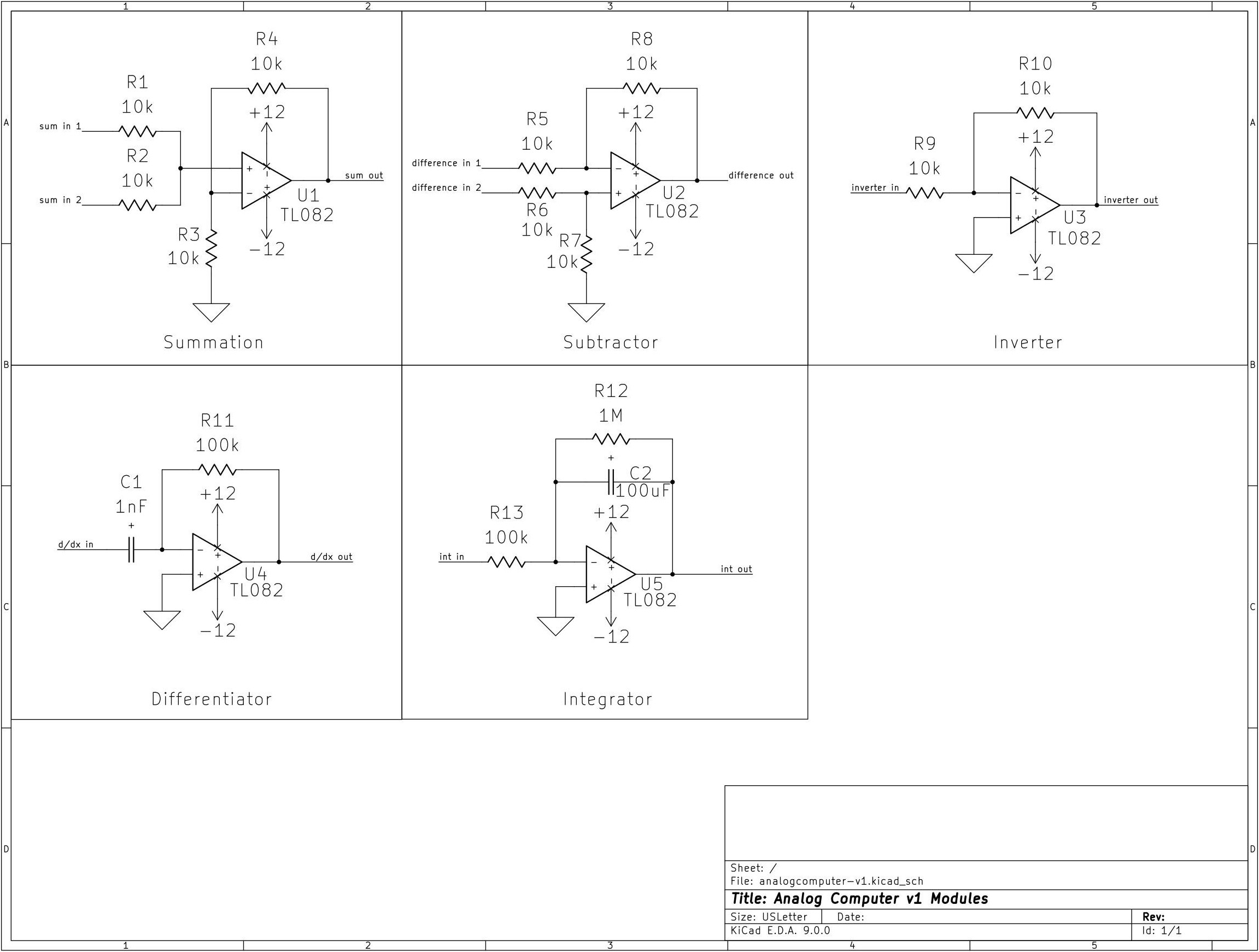
The computer can do summation, subtraction, integration, differentiation, and inverting.
The outputs can be patched into other inputs, along with an included DC voltmeter. The device takes bipolar 12V as power.
How It Works
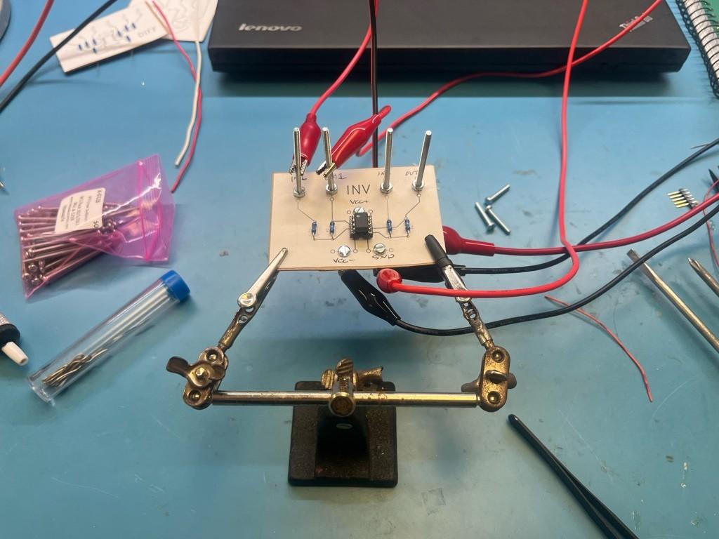
The circuits use the TL082 chip with resistors and capacitors built on paper circuit. The inputs/outputs are screws that alligator clips can clip onto.
The TL082 op-amps are in the basic configurations for their function. I tested resistor/capacitor values for a decent frequency range of around 500-15000 Hz for the calculus operations.
How to Make Your Own
This project can be reproduced using the resources provided below. Simplified,
1. Choose component values.
2. Print the paper circuits:
Sum and Difference
Integrator and Differentiator
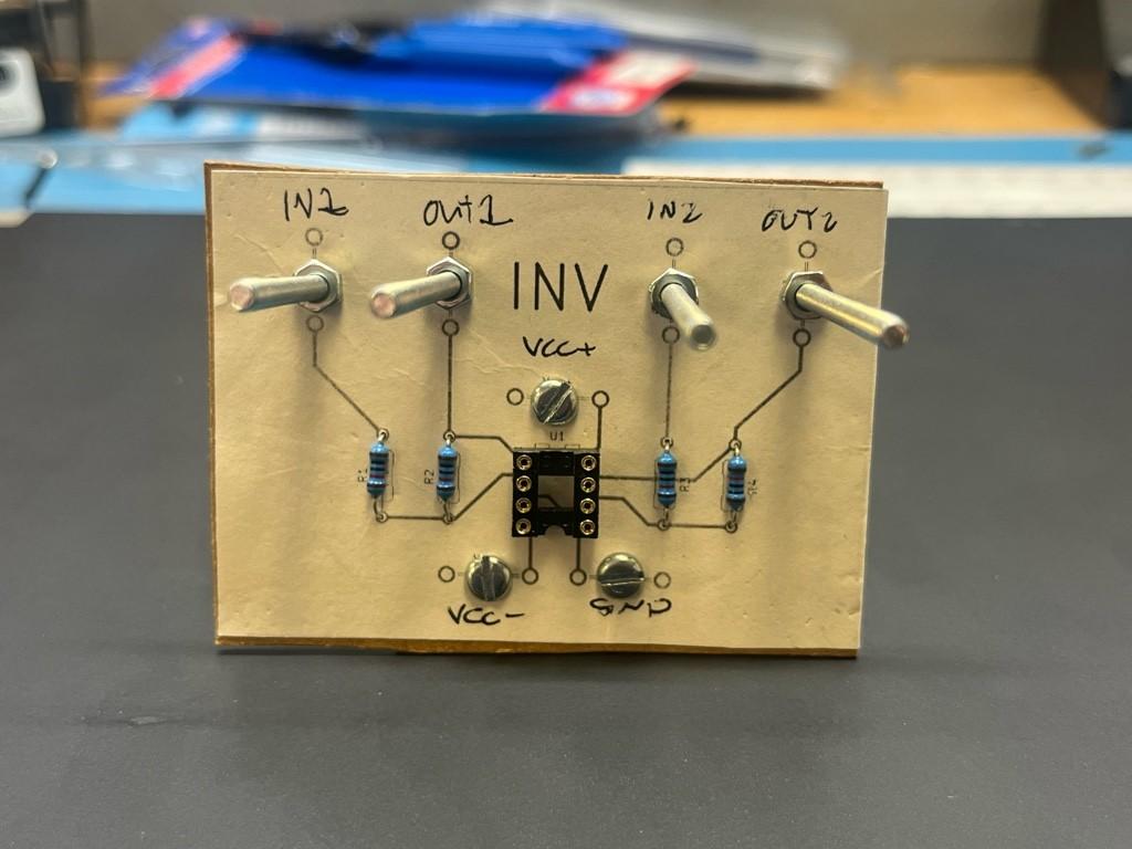
Inverter
3. Solder the paper circuits. There is a guide on how to do this below.
4. Design a panel layout, or use mine.
5. Construct a panel, whole box, or keep the paper circuits as is.
6. Wire your power and ground rails together. For this design, I used a 12V bipolar supply.
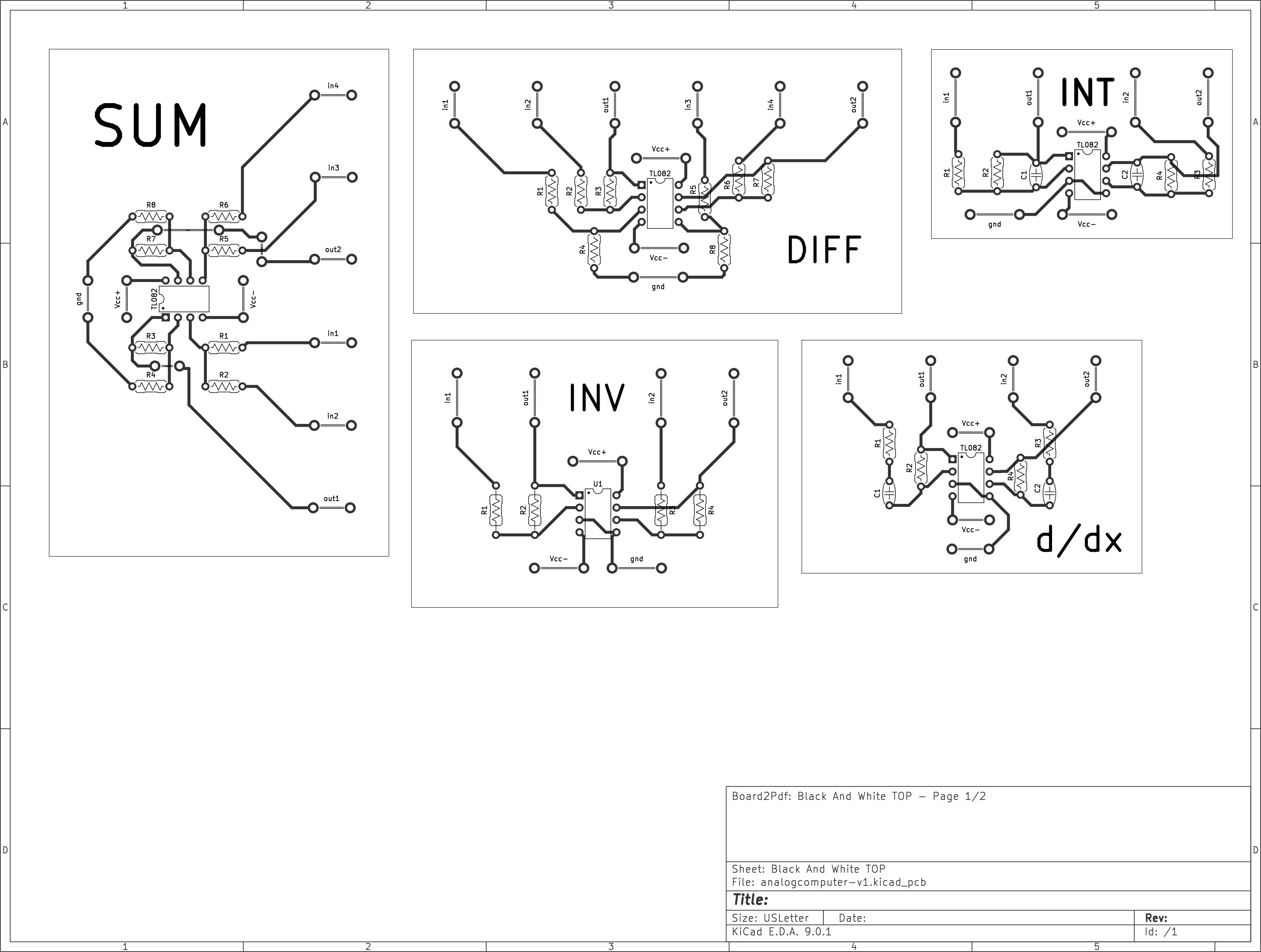
First, I started by laying out the schematics and paper circuit designs for each module. You can get the KiCad project files here.
The op-amp designs can all be understood given introductory op-amp theory. These are basic configurations.
Values were chosen based on the signals my function generator output. I recommend calculating values for your use case.
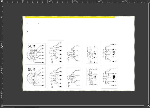
I then drew out a panel design in GIMP, carefully scaling the paper circuit modules to be print-accurate. I added power and ground pins too.
I also modeled the DC voltmeter sizing as well.
Here is a link to download the finished panel layout PDF. It prints larger than letter.
Following is a short guide on how to construct the paper circuits:
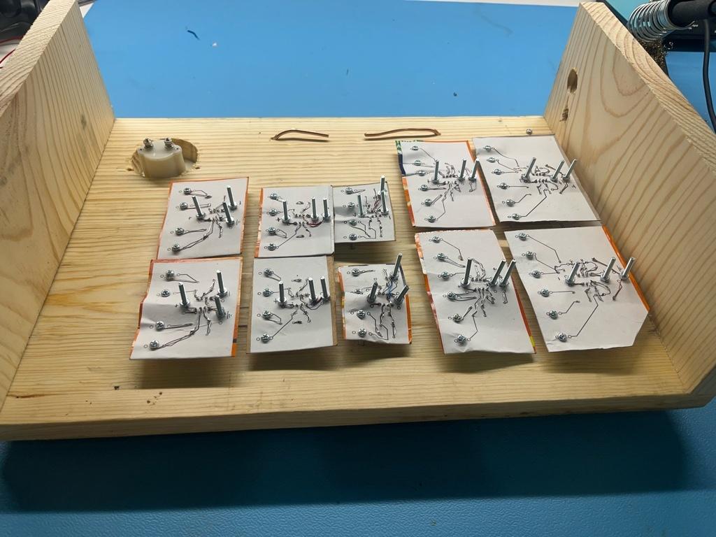
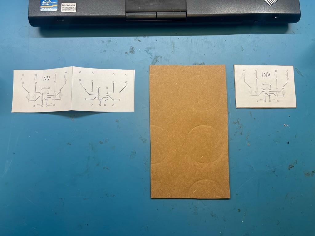
First, we start by printing and cutting out the module. Also find some suitable cardstock.
Cereal and soda boxes work well.
Fold the circuit over the line and use a glue stick to append the paper to the cardboard on both sides.
Poke leg holes through the paper circuit and place components through.
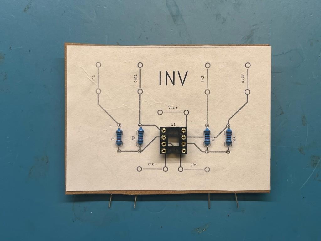
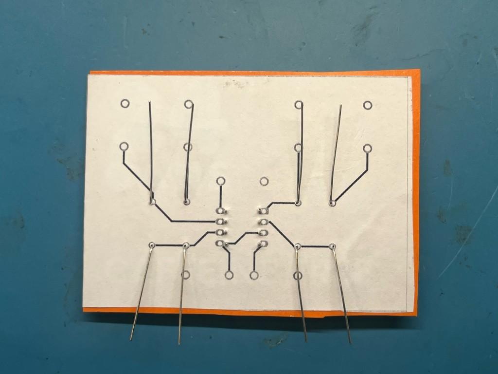
Solder the legs of the components together. The layouts are designed for this to be straight forward.
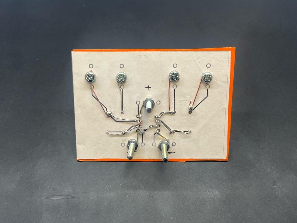
Use jumpers if needed, especially for the screw outputs/inputs.
I used the fastening nuts of the screws to electrically connect the circuit to the screws. Soldering them is near-impossible because of the heat required. The nuts can press fit.
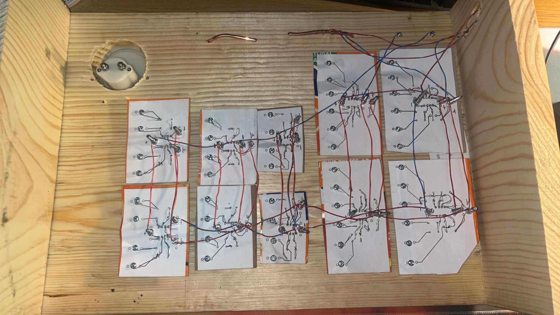
I tested each module with a function generator and an oscilloscope after to make sure they work as intended.
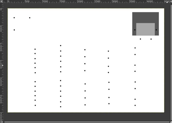
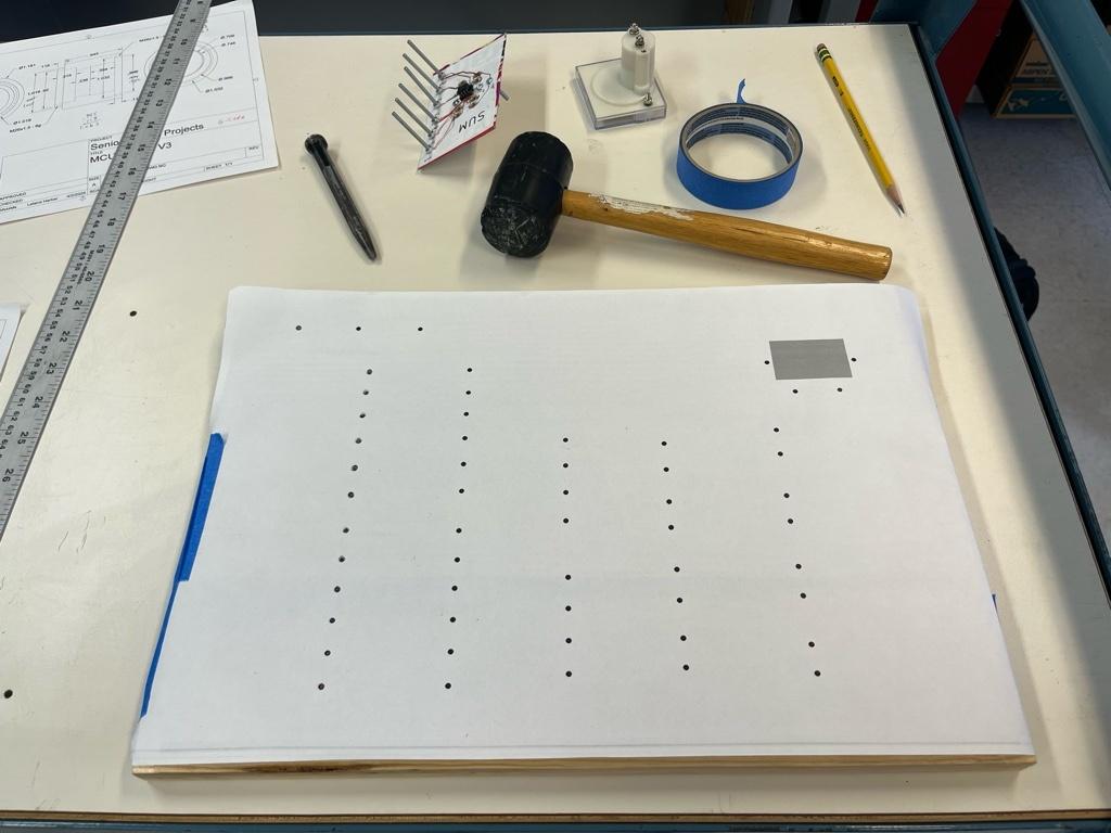
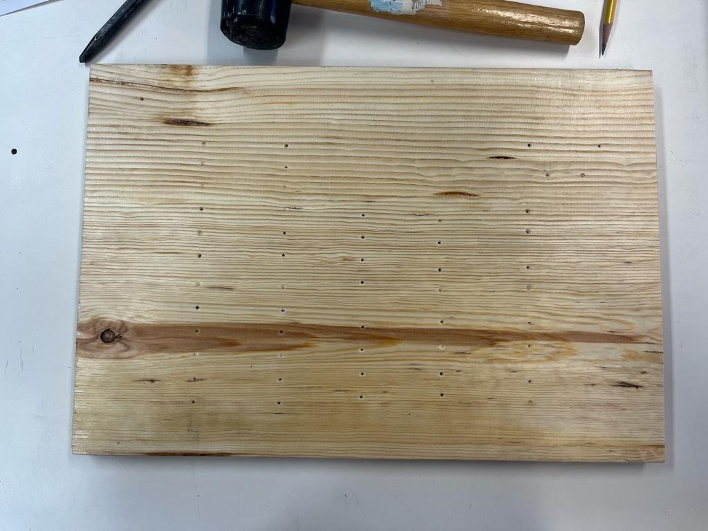
After printing out the panel layout, I taped it to the board and punched the hole template into the wood.
The wood is pine, I got it from Menards. I used a mallet and punch.
I then used a drill press to drill the holes for the paper circuits. I test fit the first few.
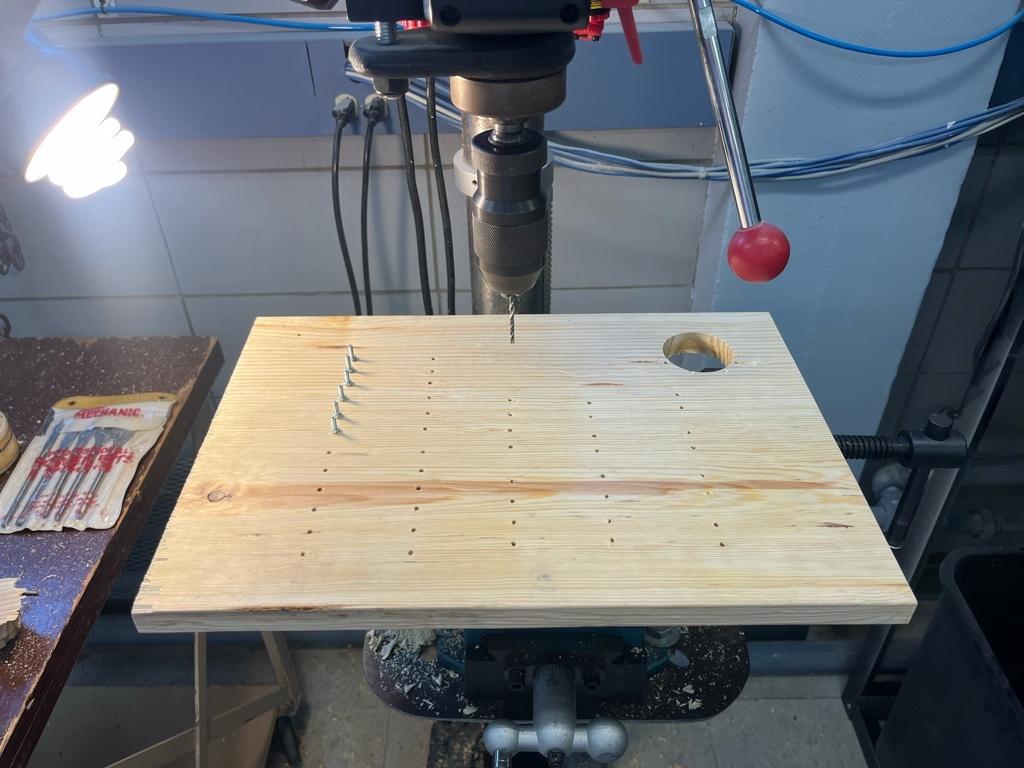
Place all the paper circuits through the drilled holes, they all had a good friction fit. I also added a large ground rail wire at the top.
Wire all the power rails together to the bipolar DC jacks.